Open System Interconnection (OSI) model, an ISO standard for worldwide communication Networks that defines a networking framework for implementing protocols in seven layers. Open Systems Interconnection (OSI) model is developed by ISO (International organization for standardization) in 1984. ISO is the organization dedicated to defining global communication and standards.


This model is called Open System Interconnection (OSI) because this model allows any two different systems to communicate regardless of their underlying architecture. Therefore OSI reference model allows open communication between different systems without requiring changes' to the logic of the underlying hardware and software.
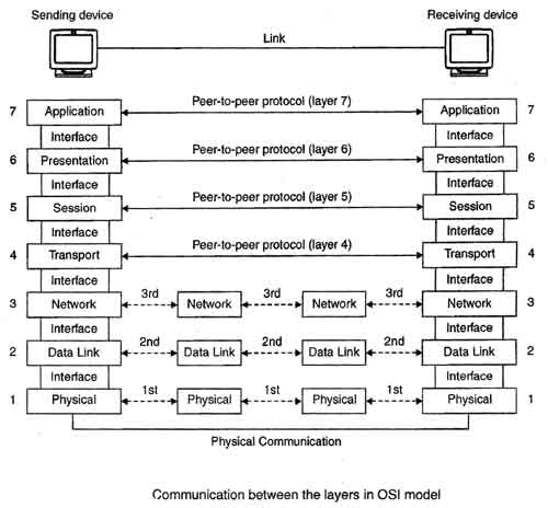
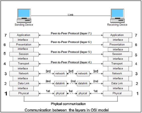
The International standard organization (ISO), in an effort to encourage open networks, developed an open systems interconnect reference model. The model logically groups the functions and sets rules, called protocols, necessary to establish and conduct communication between two or more parties. The model consists of seven functions, often referred to as layers.
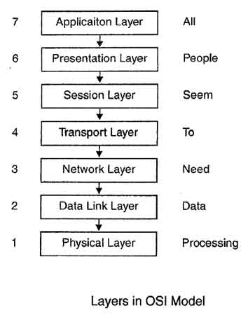
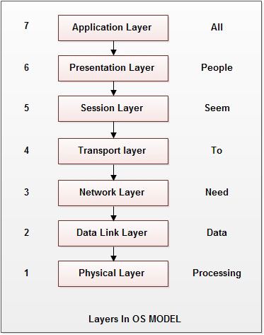
OSI reference model is a logical framework for standards for the network communication. OSI reference model is now considered as a primary standard for internetworking and inter computing. Today many network communication protocols are based on the standards of OSI model. In the OSI model the network/data communication is defined into seven layers. The seven layers can be grouped into three groups - Network, Transport and Application.
- Layer 1, 2 and 3 i.e. physical, data link, and network are network support layers.
- Layer 4, Transport layer provides end to end reliable data transmission.
- Layer 5, 6 and 7 i.e. Session, Presentation, and Application layer are user support layers.
It is important to note that OSI model is just a model. It is not a protocol that can be installed or run on any system.
To remember the names of seven layers in order one cornmon mnemonic used is -"All People Seem to Need Data Processing".
The last three layers are mainly concerned with the organization of terminal software and are not directly the concern of communications engineers. The transport layer is the one which links the communication processes to this software-oriented protocol.
Layer 7 – Application Layer
The application layer serves as the window for users and application processes to access network services. The application layer makes the interface between the program that is sending or is receiving data and the protocol stack. When you download or send emails, your e-mail program contacts this layer. This layer provides network services to the end-users like Mail, ftp, telnet, DNS.
Function of Application Layer:
- Resource sharing and device redirection.
- Remote file access.
- Remote printer access.
- Inter-process communication.
- Network management.
- Directory services.
- Electronic messaging (such as mail).
Network Virtual Terminal: A network virtual terminal is a software version of a physical terminal and allows a user to log on to a remote host. For this, application layer creates a software emulation of a terminal at the remote host. The user's computer talks to the software terminal which, in turn, talks to the host and vice-versa. The remote host believes it is communicating with one of its own terminals and allows the user to log on.
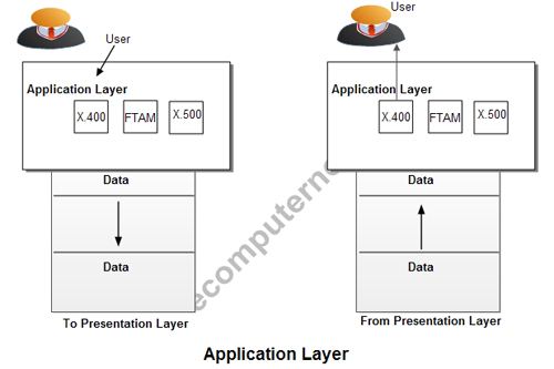
File transfer, access and management (FTAM): This application allows a user to access a file in a remote host to make changes or to read data, to retrieve files from remote computer for use in local computer, and to manage or control files in a remote computer locally.
Mail services: This application provides various e-mail services such as email forwarding and storage.
Directory services: This application provides the distributed database sources and access for global information about various objects and services.
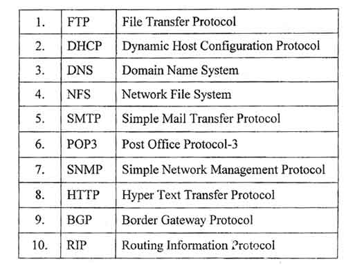
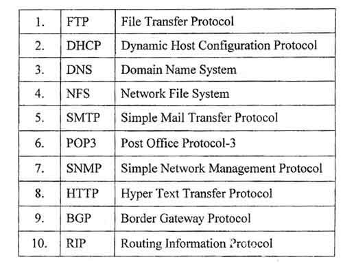
Protocols used at application layer are FTP, DNS, SNMP, SMTP, FINGER, and TELNET.
Layer 6 – Presentation Layer
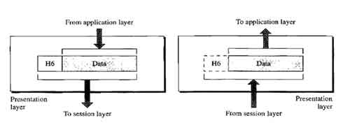
Presentation Layer is also called Translation layer. The presentation layer presents the data into a uniform format and masks the difference of data format between two dissimilar systems. The presentation layer formats the data to be presented to the application layer. It can be viewed as the translator for the network. This layer may translate data from a format used by the application layer into a common format at the sending station, and then translate the common format to a format known to the application layer at the receiving station.

Functions of Presentation Layer:
- Character code translation: for example, ASCII to EBCDIC.
- Data conversion: bit order, CR-CR/LF, integer-floating point, and so on.
- Data compression: reduces the number of bits that need to be transmitted on the network.
- Data encryption: encrypt data for security purposes. For example, password encryption.
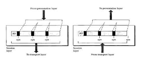
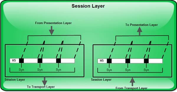
Layer 5 - Session Layer
Session layer has the primary responsibility of beginning, maintaining and ending the communication between two devices, which is called Session. It also provides for orderly communication between devices by regulating the flow of data.
The session protocol defines the format of the data sent over the connections. Session layer establish and manages the session between the two users at different ends in a network. Session layer also manages who can transfer the data in a certain amount of time and for how long.
The examples of session layers and the interactive logins and file transfer sessions. Session layer reconnect the session if it disconnects. It also reports and logs and upper layer errors. The session layer allows session establishment between processes running on different stations. The dialogue control and token management are responsibility of session layer.
Functions of Session Layer:
Session establishment, maintenance and termination: allows two application processes on different machines to establish, use and terminate a connection, called a session.
Session support: performs the functions that allow these processes to communicate over the network, performing security, name recognition, logging and so on.
Dialog control: Dialog control is the function of session layer that determines which device will communicate first and the amount of data that will be sent.
When a device is contacted first, the session layer is responsible for determining which device participating in the communication will transmit at a given time as well as controlling the amount of data that can be sent in a transmission. This is called dialog control.
The types of dialog control that can take place include simplex, half duplex and full duplex.
Dialog separation or Synchronization: The session layer is also responsible for adding checkpoint or markers within the message. This process of inserting markers to the stream of data is known as dialog separation.
Protocols: The protocols that work on the session layer are NetBIOS, Mail Slots, Names Pipes, and RPC.
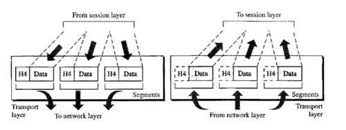
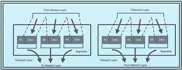
Layer 4 – Transport Layer
Transport layer manages end to end (source to destination) (process to process) message delivery in a network and also provides the error checking and hence guarantees that no duplication or errors are occurring in the data transfers across the network. It makes sure that all the packets of a message arrive intact and in order.
Transport layer also provides the acknowledgement of the successful data transmission and retransmits the data if error is found. The transport layer ensures that messages are delivered error-free, in sequence, and with no losses or duplications.
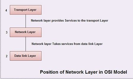
The size and complexity of a transport protocol depends on the type of service it can get from the network layer.Transport layer is at the core of OSI model. Transport layer provides services to application layer and takes services from network layer.
Transport layer divides the message received from upper layer into packets at source and reassembles these packets again into message at the destination.
Transport layer provides two types of services:
1. Connection oriented
2. Connectionless
1. Connection Oriented Transmission
(a) In this type of transmission the receiving device sends an acknowledgment, back to the source after a packet or group of packet is received.
(b) This type of transmission is also known as reliable transport method.
(c) Because connection oriented transmission requires more packets be sent across network, it is considered a slower transmission method.
(d) If the data that is sent has problems, the destination requests the source for retransmission by acknowledging only packets that have been received and are recognizable.
(e) Once the destination computer receives all of the data necessary to reassemble the packet, the transport layer assembles the data in the correct sequence and then passes it up, to the session layer.
2. Connectionless Transmission
(a) In this type of transmission the receiver does not acknowledge receipt of a packet.
(b) Sending device assumes that packet arrive just fine.
(c) This approach allows for much faster communication between devices.
(d) The trade-off is that connectionless transmission is less reliable than connection oriented.
Functions of Transport Layer:
Segmentation of message into packet and reassembly of packets into message: accepts a message from the (session) layer above it, splits the message into smaller units (if not already small enough), and passes the smaller units down to the network layer. The transport layer at the destination station reassembles the message.
Message acknowledgment: provides reliable end-to-end message delivery with acknowledgments.
Message traffic control: tells the transmitting station to "back-off" when no message buffers are available.
Session multiplexing: multiplexes several message streams, or sessions onto one logical link and keeps track of which messages belong to which sessions.
Service point addressing: The purpose of transport layer is to delivery message from one process running on source machine to another process running on destination machine. It may be possible that several programs or processes are running on both the machines at a time. In order to delivery the message to correct process, transport layer header includes a type of address called service point address or port address. Thus by specifying this address, transport layer makes sure that the message is delivered to the correct process on destination machine.
Flow control: Like Data link layer, transport layer also performs flow control. Transport layer makes sure that the sender and receiver communicate at a rate they both can handle. Therefore flow control prevents the source from sending data packets faster than the destination can handle. Here, flow control is performed end-to-end rather than across a link.
Error control: Like Data link layer, Transport layer also performs error control. Here error control is performed end-to-end rather than across a single link. The sending transport layer ensures that the entire message arrives at the receiving transport layer without error (damage, loss or duplication). Error correction is achieved through retransmission.
Protocols: These protocols work on the transport layer TCP, SPX, NETBIOS, ATP and NWLINK.
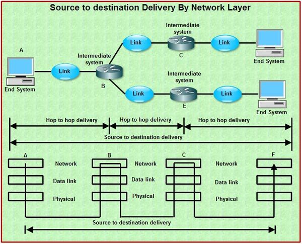
Layer 3 – Network Layer
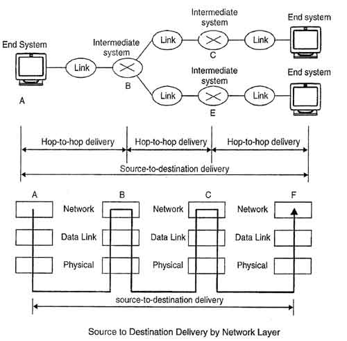
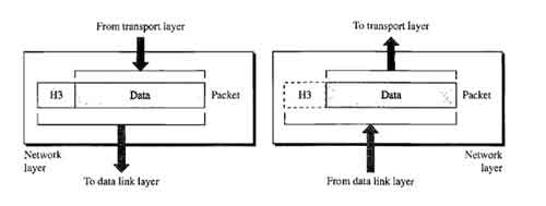
This layer is incharge of packet addressing, converting logical addresses into physical addresses. It is responsible for the source-to-destination delivery of a packet across multiple networks (links). This layer is also incharge of setting the routing. The packets will use to arrive at their destination, based on factors like traffic and priorities. The network layer determines that how data transmits between the network devices.
If two systems are connected to same link, then there is no need for network layer. And if two systems are attached to different networks with connecting devices like routers between the networks, then there is need for the network layer.
It also translates the logical address into the physical address e.g computer name into MAC address. It is also responsible for defining the route, it managing the network problems and addressing The network layer controls the operation of the subnet, deciding which physical path the data should take based on network conditions, priority of service, and other factors. The X.25 protocols works at the physical, data link, and network layers.
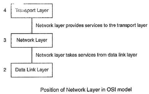
The network layer lies between data link kyer and transport layer. It takes services from Data link and provides services to the transport layer.
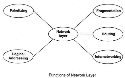
Functions of Network Layer:
• Subnet Traffic Control: Routers (network layer intermediate systems) can instruct a sending station to "throttle back" its frame transmission when the router's buffer fills up.
• Logical-Physical Address Mapping: translates logical addresses, or names, into physical addresses.
• Subnet Usage Accounting: has accounting functions to keep track of frames forwarded by subnet intermediate systems, to produce billing information.
In the network layer and the layers below, peer protocols exist between a node and its immediate neighbor, but the neighbor may be a node through which data is routed, not the destination station. The source and destination stations may be separated by many intermediate systems.
Internetworking
• One of the main responsibilities of network layer is to provide internetworking between different networks.
• It provides logical connection between different types of network.
• It is because of this layer, we can combine various different networks to form a bigger network.
Logical Addressing
• Large number of different networks can be combined together to from bigger networks or internetwork.
• In order to identify each device on internetwork uniquely, network layer defines an addressing scheme.
• Such an address distinguishes each device uniquely and universally.
Routing
• When independent networks or links are combined together to create internet works, multiple routes are possible from source machine to destination machine.
• The network layer protocols determine which route or path is best from source to destination. This function of network layer is known as routing.
• Routes frames among networks.
Packetizing
• The network layer receives the data from the upper layers and creates its own packets by encapsulating these packets. The process is known as packetizing.
• This packetizing in done by Internet Protocol (IP) that defines its own packet format.
Fragmentation
• Fragmentation means dividing the larger packets into small fragments.
• The maximum size for a transportable packet in defined by physical layer protocol.
• For this, network layer divides the large packets into fragments so that they can be easily sent on the physical medium.
• If it determines that a downstream router's maximum transmission unit (MTU) size is less than the frame size, a router can fragment a frame for transmission and re-assembly at the destination station.
Protocols: These protocols work on the network layer IP, ICMP, ARP, RIP, OSI, IPX and OSPF.

Layer 2 - Data Link layer
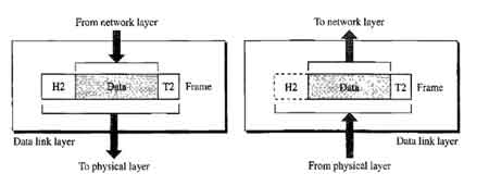
It is responsible for reliable node-to-node delivery of data. It receives the data from network layer and creates frames, add physical address to these frames and pass them to physical layer
The data link layer provides error-free transfer of data frames from one node to another over the physical layer, allowing layers above it to assume virtually error-free transmission over the link. Data Link layer defines the format of data on the network. A network data frame, packet, includes checksum, source and destination address, and data.
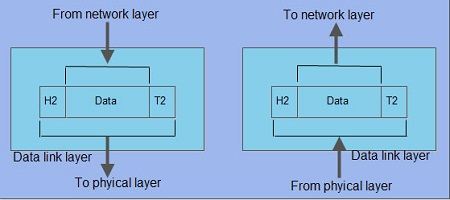
The data link layer handles the physical and logical connections to the packet's destination, using a network interface. This layer gets the data packets send by the network layer and convert them into frames that will be sent out to the network media, adding the physical address of the network card of your computer, the physical address of the network card of the destination, control data and a checksum data, also known as CRC. The X.25 protocols works at the physical, data link, and network layers.
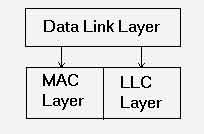
Data Link layer consists of two sub-layers
1. Logical Link Control (LLC) sublayer
2. Medium Access Control (MAC) sublayer
LLC sublayer provides interface between the media access methods and network layer protocols such as Internet protocol which is a part of TCP/IP protocol suite.
LLC sublayer determines whether the communication is going to be connectionless or connection-oriented at the data link layer.
MAC sublayer is responsible for connection to physical media. At the MAC sublayer of Data link layer, the actual physical address of the device, called the MAC address is added to the packet. Such a packet is called a Frame that contains all the addressing information necessary to travel from source device to destination device.

MAC address is the 12 digit hexadecimal number unique to every computer in this world. A device's MAC address is located on its Network Interface Card (NIC). In these 12 digits of MAC address, the first six digits indicate the NIC manufacturer and the last six digits are unique. For example, 32-14-a6-42-71-0c is the 12 digit hexadecimal MAC address. Thus MAC address represents the physical address of a device in the network.
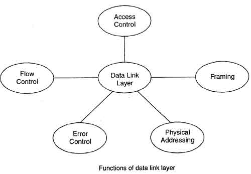
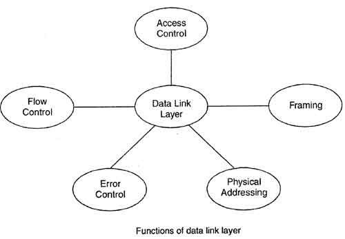
Functions of Data Link Layer:
Link Establishment and Termination: Establishes and terminates the logical link between two nodes.
Physical addressing: After creating frames, Data link layer adds physical addresses (MAC address) of sender and/or receiver in the header of each frame.
Frame Traffic Control: Tells the transmitting node to "back-off algorithm" when no frame buffers are available.
Frame Sequencing: Transmits/receives frames sequentially.
Frame Acknowledgment: Provides/expects frame acknowledgments. Detects and recovers from errors that occur in the physical layer by retransmitting non-acknowledged frames and handling duplicate frame receipt.
Frame Delimiting: Creates and recognizes frame boundaries.
Frame Error Checking: Checks received frames for integrity.
Media Access Management: determines when the node "has the right" to use the physical medium.
Flow control: It is the traffic regulatory mechanism implemented by Data Link layer that prevents the fast sender from drowning the slow receiver. If the rate at which data is absorbed by receiver is less that the rate produced in the sender, the data link layer imposes this flow control mechanism.
Error control: Data link layer provides the mechanism of error control in which it detects and retransmits damaged· or lost frames. It also deals with the problem of duplicate frame, thus providing reliability to physical layer.
Access control: When a single communication channel is shared by multiple devices, MAC sub-layer of data link layer helps to determine which device has control over the channel at a given time.
Feedback: After transmitting the frames, the system waits for the feedback. The receiving device then sends the acknowledgement frames back to the source providing the receipt of the frames.
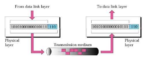
Layer 1 – Physical Layer
The physical layer, the lowest layer of the OSI model, is concerned with the transmission and reception of theunstructured raw bit stream over a physical medium. It describes the electrical/optical, mechanical, and functional interfaces to the physical medium, and carries the signals for all of the higher layers. Physical layer defines the cables, network cards and physical aspects.
It is responsible for the actual physical connection between the devices. Such physical connection may be made by using twisted pair cable, fiber-optic, coaxial cable or wireless communication media. This layer gets the frames sent by the Data Link layer and converts them into signals compatible with the transmission media. If a metallic cable is used, then it will convert data into electrical signals; if a fiber optical cable is used, then it will convert data into luminous signals; if a wireless network is used, then it will convert data into electromagnetic signals; and so on.
When receiving data, this layer will get the signal received and convert it into 0s and 1s and send them to the Data Link layer, which will put the frame back together and check for its integrity The X.25 protocols works at the physical, data link, and network layers.
Functions of Physical layer:
Data Encoding: Modifies the simple digital signal pattern (1s and 0s) used by the PC to better accommodate the characteristics of the physical medium, and to aid in bit and frame synchronization. It determines:
- What signal state represents a binary 1?
- How the receiving station knows when a "bit-time" starts.
- How the receiving station delimits a frame.
Physical Medium Attachment, Accommodating Various Possibilities in the Medium:
- Will an external transceiver (MAU) be used to connect to the medium?
- How many pins do the connectors have and what is each pin used for?
Transmission Technique: determines whether the encoded bits will be transmitted by baseband (digital) or broadband (analog) signaling.
Physical Medium Transmission: transmits bits as electrical or optical signals appropriate for the physical medium, and determines:
- What physical medium options can be used.
- How many volts/db should be used to represent a given signal state, using a given physical medium.
Protocols used at physical layer are ISDN, IEEE 802 and IEEE 802.2.
Bit synchronization: The physical layer provides the synchronization of the bits by providing a clock. This clock controls both transmitter as well as receiver thus providing synchronization at bit level.
Provides physical characteristics of interfaces and medium: Physical layer manages the way a device connects to network media. For example, if the physical connection from the device to the network uses coaxial cable, the hardware that functions at the physical layer will be designed for that specific type of network. All components including connectors are also specified at physical layer.
Bit rate control: Physical layer defines the transmission rate i.e. the number of bits sent in one second. Therefore it defines the duration of a bit.
Line configuration: Physical layer also defines the way in which the devices are connected to the medium. Two different line configurations are used point to point configuration and multipoint configuration. To activate, maintain and deactivate the physical connection.
Transmission mode: Physical layer also defines the way in which the data flows between the two connected devices. The various transmission modes possible are: Simplex, half-duplex and full-duplex.
Physical topologies: Physical layer specifies the way in which the different, devices/nodes are arranged in a networki.e. bus, star or mesh.
Multiplexing: Physical layer can use different techniques of multiplexing, in order to improve the channel efficiency.
Circuit switching: Physical layer also provides the circuit switching to interconnect different networks.