IP Datagram General Format
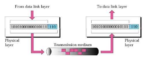
Data transmitted over an internet using IP is carried in messages called IP datagrams. Like all network protocol messages, IP uses a specific format for its datagrams. We are of course looking here at IP version 4 and so we will examine the IPv4 datagram format, which was defined in RFC 791 along with the rest of IPv4.
The IPv4 datagram is conceptually divided into two pieces: the header and the payload. The header contains addressing and control fields, while the payload carries the actual data to be sent over the internetwork. Unlike some message formats, IP datagrams do not have a footer following the payload.
Even though IP is a relatively simple, connectionless, “unreliable” protocol, the IPv4 header carries a fair bit of information, which makes it rather large. At a minimum, it is 20 bytes long, and with options can be significantly longer. The IP datagram format is described in Table 56 and illustrated in Figure 86.
Field Name
|
Size (bytes)
|
Description
|
Version
|
1/2
(4 bits) |
Version: Identifies the version of IP used to generate the datagram. For IPv4, this is of course the number 4. The purpose of this field is to ensure compatibility between devices that may be running different versions of IP. In general, a device running an older version of IP will reject datagrams created by newer implementations, under the assumption that the older version may not be able to interpret the newer datagram correctly.
|
IHL
|
1/2
(4 bits) |
Internet Header Length (IHL): Specifies the length of the IP header, in 32-bit words. This includes the length of any options fields and padding. The normal value of this field when no options are used is 5 (5 32-bit words = 5*4 = 20 bytes). Contrast to the longer Total Lengthfield below.
|
TOS
|
1
|
Type Of Service (TOS): A field designed to carry information to provide quality of service features, such as prioritized delivery, for IP datagrams. It was never widely used as originally defined, and its meaning has been subsequently redefined for use by a technique calledDifferentiated Services (DS). See below for more information.
|
TL
|
2
|
Total Length (TL): Specifies the total length of the IP datagram, in bytes. Since this field is 16 bits wide, the maximum length of an IP datagram is 65,535 bytes, though most are much smaller.
|
Identification
|
2
|
Identification: This field contains a 16-bit value that is common to each of the fragments belonging to a particular message; for datagrams originally sent unfragmented it is still filled in, so it can be used if the datagram must be fragmented by a router during delivery. This field is used by the recipient to reassemble messages without accidentally mixing fragments from different messages. This is needed because fragments may arrive from multiple messages mixed together, since IP datagrams can be received out of order from any device. See the discussion of IP message fragmentation.
|
Flags
|
3/8
(3 bits) | 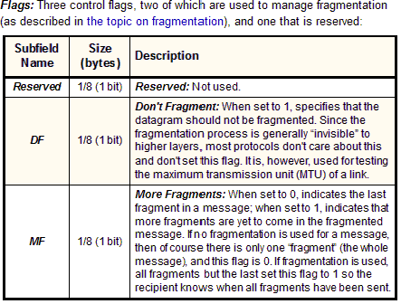 |
Fragment Offset
|
1 5/8
(13 bits) |
Fragment Offset: When fragmentation of a message occurs, this field specifies the offset, or position, in the overall message where the data in this fragment goes. It is specified in units of 8 bytes (64 bits). The first fragment has an offset of 0. Again, see the discussion of fragmentation for a description of how the field is used.
|
TTL
|
1
|
Time To Live (TTL): Short version: Specifies how long the datagram is allowed to “live” on the network, in terms of router hops. Each router decrements the value of the TTL field (reduces it by one) prior to transmitting it. If the TTL field drops to zero, the datagram is assumed to have taken too long a route and is discarded.
See below for the longer explanation of TTL. |
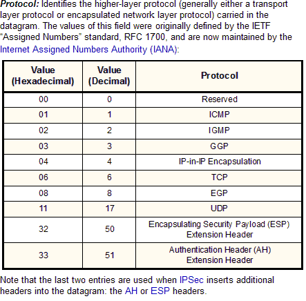
Protocol
|
1
|  |
Header Checksum
|
2
|
Header Checksum: A checksum computed over the header to provide basic protection against corruption in transmission. This is not the more complex CRC code typically used by data link layer technologies such as Ethernet; it's just a 16-bit checksum. It is calculated by dividing the header bytes into words (a word is two bytes) and then adding them together. The data is not checksummed, only the header. At each hop the device receiving the datagram does the same checksum calculation and on a mismatch, discards the datagram as damaged.
|
Source Address
|
4
|
Source Address: The 32-bit IP address of the originator of the datagram. Note that even though intermediate devices such as routers may handle the datagram, they do not normally put their address into this field—it is always the device that originally sent the datagram.
|
Destination Address
|
4
|
Destination Address: The 32-bit IP address of the intended recipient of the datagram. Again, even though devices such as routers may be the intermediate targets of the datagram, this field is always for the ultimate destination.
|
Options
|
Variable
|
Options: One or more of several types of options may be included after the standard headers in certain IP datagrams. I discuss them in the topic that follows this one.
|
Padding
|
Variable
|
Padding: If one or more options are included, and the number of bits used for them is not a multiple of 32, enough zero bits are added to “pad out” the header to a multiple of 32 bits (4 bytes).
|
Data
|
Variable
|
Data: The data to be transmitted in the datagram, either an entire higher-layer message or a fragment of one.
|
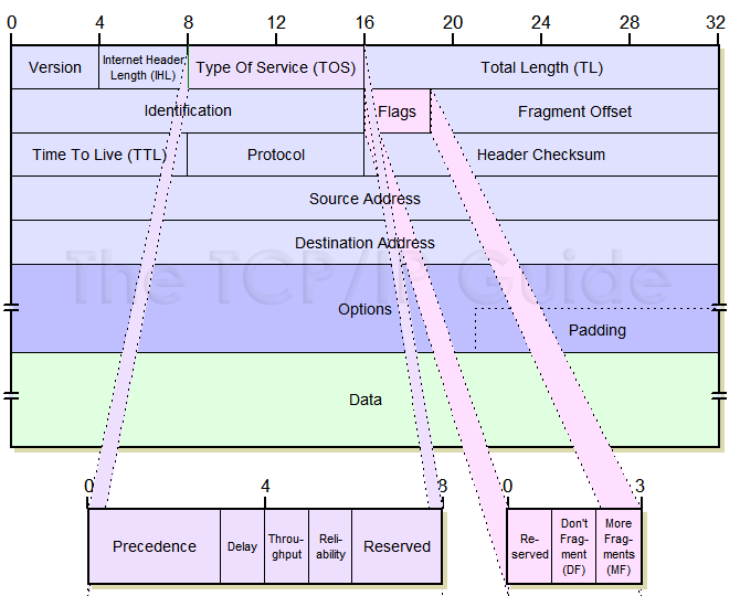 |
That’s a pretty big table, because the IP datagram format is pretty important and has a lot of fields that need explaining. To keep it from being even longer, I decided to move a couple of the more complex descriptions out of the table.
Time To Live (TTL) Field
Since IP datagrams are sent from router to router as they travel across an internetwork, it is possible that a situation could result where a datagram gets passed from router A to router B to router C and then back to router A. Router loops are not supposed to happen, and rarely do, but are possible.
To ensure that datagrams don't circle around endlessly, the TTL field was intended to be filled in with a time value (in seconds) when a datagram was originally sent. Routers would decrease the time value periodically, and if it ever hit zero, the datagram would be destroyed. This was also intended to be used to ensure that time-critical datagrams wouldn’t linger past the point where they would be “stale”.
In practice, this field is not used in exactly this manner. Routers today are fast and usually take far less than a second to forward a datagram; measuring the time that a datagram “lives” would be impractical. Instead, this field is used as a “maximum hop count” for the datagram. Each time a router processes a datagram, it reduces the value of the TTL field by one. If doing this results in the field being zero, the datagram is said to have expired. It is dropped, and usually an ICMP Time Exceededmessage is sent to inform the originator of the message that this happened.
The TTL field is one of the primary mechanisms by which networks are protected from router loops (see the description of ICMP Time Exceeded messages for more on how TTL helps IP handle router loops.)
Type Of Service (TOS) Field
This one-byte field was originally intended to provide certain quality of service features for IP datagram delivery. It allowed IP datagrams to be tagged with information indicating not only their precedence, but the preferred manner in which they should be delivered. It was divided into a number of subfields, as shown in Table 57 (andFigure 86).
The lack of quality of service features has been considered a weakness of IP for a long time. But as we can see in Table 57, these features were built into IP from the start. What's going on here? The answer is that even though this field was defined in the standard back in the early 1980s, it was not widely used by hardware and software. For years, it was just passed around with all zeroes in the bits and mostly ignored.
Subfield Name
|
Size (bytes)
|
Description
|
Precedence
|
3/8
(3 bits) | 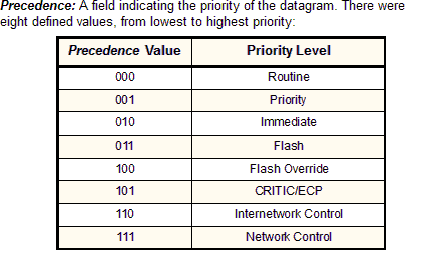 |
D
|
1/8
(1 bit) |
Delay: Set to 0 to request “normal” delay in delivery; set to 1 if low delay delivery is requested.
|
T
|
1/8
(1 bit) |
Throughput: Set to 0 to request “normal” delivery throughput; set to 1 if higher throughput delivery is requested.
|
R
|
1/8
(1 bit) |
Reliability: Set to 0 to request “normal” reliability in delivery; set to 1 if higher reliability delivery is requested.
|
Reserved
|
2/8
(2 bits) |
Reserved: Not used.
|
The IETF, seeing the field unused, attempted to revive its use. In 1998, RFC 2474 redefines the first six bits of the TOS field to support a technique called Differentiated Services (DS). Under DS, the values in the TOS field are called codepoints and are associated with different service levels. This starts to get rather complicated, so refer to RFC 2474 if you want all the details.
Understanding the IP datagram format is an important part of troubleshooting IP networks. Be sure to see the following topic on options for more information on how IP options are used in datagrams, and the topic on fragmenting for some more context on the use of fragmentation-related fields such as Identification, Fragment Offset, and More Fragments.