Bluetooth - What is Bluetooth?
• Bluetooth is a wireless LAN technology used to connect devices of different functions such as telephones, computers (laptop or desktop), notebooks, cameras, printers and so on
. Bluetooth project was started by SIG (Special Interest Group) formed by four companies - IBM, Intel, Nokia and Toshiba for interconnecting computing and communicating devices using short-range, lower-power, inexpensive wireless radios.
• The project was named Bluetooth after the name of Viking king – Harald Blaatand who unified Denmark and Norway in 10th century.
• Nowadays, Bluetooth technology is used for several computer and non computer application:
1. It is used for providing communication between peripheral devices like wireless mouse or keyboard with the computer.
2. It is used by modern healthcare devices to send signals to monitors.
3. It is used by modern communicating devices like mobile phone, PDAs, palmtops etc to transfer data rapidly.
5. It is used for cordless telephoning to connect a handset and its local base station.
6. It also allows hands-free voice comml1nication with headset.
7. It also enables a mobile computer to connect to a fixed LAN.
8. It can also be used for file transfer operations from one mobile phone to another.
Bluetooth devices have a built-in short range radio transmitter. The rate provided is 1Mbps and uses 2.4 GHz bandwidth.
Bluetooth Architecture
Bluetooth architecture defines two types of networks:
1. Piconet
2. Scattemet
1. Piconet
• Piconet is a Bluetooth network that consists of one primary (master) node and seven active secondary (slave) nodes.
• Thus, piconet can have upto eight active nodes (1 master and 7 slaves) or stations within the distance of 10 meters.
• There can be only one primary or master station in each piconet.
• The communication between the primary and the secondary can be one-to-one or one-to-many.
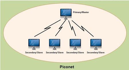
• All communication is between master and a slave. Salve-slave communication is not possible.
• In addition to seven active slave station, a piconet can have upto 255 parked nodes. These parked nodes are secondary or slave stations and cannot take part in communication until it is moved from parked state to active state.
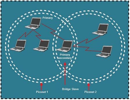
2. Scatternet
• Scattemet is formed by combining various piconets.
• A slave in one piconet can act as a master or primary in other piconet.
• Such a station or node can receive messages from the master in the first piconet and deliver the message to its slaves in other piconet where it is acting as master. This node is also called bridge slave.
• Thus a station can be a member of two piconets.
• A station cannot be a master in two piconets.
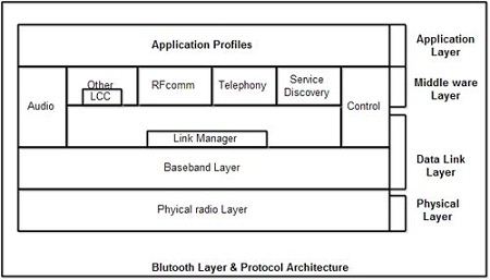
Bluetooth layers and Protocol Stack
• Bluetooth standard has many protocols that are organized into different layers.
• The layer structure of Bluetooth does not follow OS1 model, TCP/IP model or any other known model.
• The different layers and Bluetooth protocol architecture.
Radio Layer
• The Bluetooth radio layer corresponds to the physical layer of OSI model.
• It deals with ratio transmission and modulation.
• The radio layer moves data from master to slave or vice versa.
• It is a low power system that uses 2.4 GHz ISM band in a range of 10 meters.
• This band is divided into 79 channels of 1MHz each. Bluetooth uses the Frequency Hopping Spread Spectrum (FHSS) method in the physical layer to avoid interference from other devices or networks.
• Bluetooth hops 1600 times per second, i.e. each device changes its modulation frequency 1600 times per second.
• In order to change bits into a signal, it uses a version of FSK called GFSK i.e. FSK with Gaussian bandwidth filtering.
Baseband Layer
• Baseband layer is equivalent to the MAC sublayer in LANs.
• Bluetooth uses a form of TDMA called TDD-TDMA (time division duplex TDMA).
• Master and slave stations communicate with each other using time slots.
• The master in each piconet defines the time slot of 625 µsec.
• In TDD- TDMA, communication is half duplex in which receiver can send and receive data but not at the same time.
• If the piconet has only no slave; the master uses even numbered slots (0, 2, 4, ...) and the slave uses odd-numbered slots (1, 3, 5, .... ). Both master and slave communicate in half duplex mode. In slot 0, master sends & secondary receives; in slot 1, secondary sends and primary receives.
• If piconet has more than one slave, the master uses even numbered slots. The slave sends in the next odd-numbered slot if the packet in the previous slot was addressed to it.
• In Baseband layer, two types of links can be created between a master and slave. These are:
1. Asynchronous Connection-less (ACL)
• It is used for packet switched data that is available at irregular intervals.
• ACL delivers traffic on a best effort basis. Frames can be lost & may have to be retransmitted.
• A slave can have only one ACL link to its master.
• Thus ACL link is used where correct delivery is preferred over fast delivery.
• The ACL can achieve a maximum data rate of 721 kbps by using one, three or more slots.
2. Synchronous Connection Oriented (SCO)
• sco is used for real time data such as sound. It is used where fast delivery is preferred over accurate delivery.
• In an sco link, a physical link is created between the master and slave by reserving specific slots at regular intervals.
• Damaged packet; are not retransmitted over sco links.
• A slave can have three sco links with the master and can send data at 64 Kbps.
Logical Link, Control Adaptation Protocol Layer (L2CAP)
• The logical unit link control adaptation protocol is equivalent to logical link control sublayer of LAN.
• The ACL link uses L2CAP for data exchange but sco channel does not use it.
• The various function of L2CAP is:
1. Segmentation and reassembly
• L2CAP receives the packets of upto 64 KB from upper layers and divides them into frames for transmission.
• It adds extra information to define the location of frame in the original packet.
• The L2CAP reassembles the frame into packets again at the destination.
2. Multiplexing
• L2CAP performs multiplexing at sender side and demultiplexing at receiver side.
• At the sender site, it accepts data from one of the upper layer protocols frames them and deliver them to the Baseband layer.
• At the receiver site, it accepts a frame from the baseband layer, extracts the data, and delivers them to the appropriate protocol1ayer.
3. Quality of Service (QOS)
• L2CAP handles quality of service requirements, both when links are established and during normal operation.
• It also enables the devices to negotiate the maximum payload size during connection establishment.
Bluetooth Frame Format
The various fields of blue tooth frame format are:
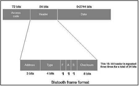
1. Access Code: It is 72 bit field that contains synchronization bits. It identifies the master.
2. Header: This is 54-bit field. It contain 18 bit pattern that is repeated for 3 time.
The header field contains following subfields:
(i) Address: This 3 bit field can define upto seven slaves (1 to 7). If the address is zero, it is used for broadcast communication from primary to all secondaries.
(ii)Type: This 4 bit field identifies the type of data coming from upper layers.
(iii) F: This flow bit is used for flow control. When set to 1, it means the device is unable to receive more frames.
(iv) A: This bit is used for acknowledgement.
(v) S: This bit contains a sequence number of the frame to detect retransmission. As stop and wait protocol is used, one bit is sufficient.
(vi) Checksum: This 8 bit field contains checksum to detect errors in header.
3. Data: This field can be 0 to 2744 bits long. It contains data or control information coming from upper layers
No comments:
Post a Comment